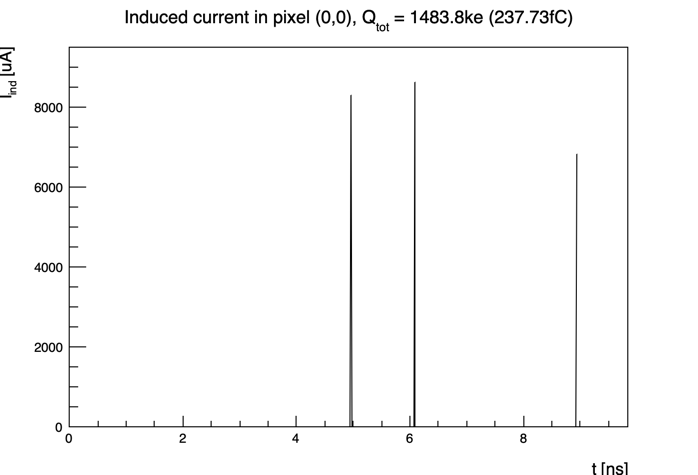
I am having trouble setting up something in Allpix (which I also haven’t attempted to do before). At UoManchester (UK), we have a single-pixel diode setup (like in [allpix_source]/examples/simple_diode/) which we can characterize using the TPA (Two-Photon Absorption) technique. I would like to have a precise simulation of the signal shape generated by a voxel of configurable size inside the sensor. I have seen (and heard) that the signal shape from a single e-h pair in pretty “boxy” (like in Figure 3 of this paper), but I have failed to reproduce some thing similar with the propagation modules in Allpix. I think I know how to use the [DepositionPointCharge] to describe voxels, but the fundamental problem that I seem to have is I cannot get to have realistic signal shapes. I am attaching an image that comes with the output plots of the [PulseTransfer] module:
It’s hard to pinpoint potential issues from the information I have available just now. Could you elaborate a bit (or post the configurations you are running? A few things to consider:
We’re dealing with MC simulations, so we are subject to fluctuations. When we look at pulse shapes, we always generate several pulses (a few tens or hundreds) from the same starting position, and then average those to get a nice pulse
Make sure to use a small time stepping, depending on the detector something like 10ps might be worth looking at.
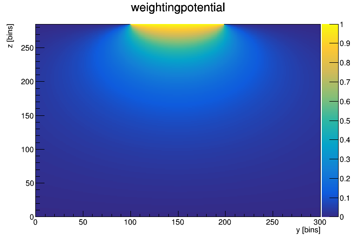
Make sure the weighting potential you are using is matching the electric field. How does the weighting potential and electric field maps look like that the respective readers produce for you?
Does the integrated charge match your expectation? How much do you deposit initially? Are you sure the time axis doesn’t cut off the actual pulse?
An example from a recent simulation from our group comparing a TCAD simulation with an (averaged) APSQ simulation using the electrostatic TCAD fields:
Many thanks for the reply. I guess I do have one question which does not seem clear to me. I can generate very nice weighting potentials via the generate_potential executable, see:
(this is for the cmsp1 model in the [allpix]/models/ directory). How do I convert that into an Electric Field (init format), which should be just the gradient of the potential (for use in the [ElectricFieldReader] Module)?
if you have a diode for characterization, I would guess that the weighting potential is not really accurate. These diodes normally have an implant and electrode that covers a large fraction (or all) of the surface - in the model that would mean adjusting the implant_size parameter to cover the full pixel. We can also limit the size of the potential to a single pixel.
You should then have a weighting potential that essentially is linear in z with little to no x/y dependence, and you can then use a linear electric field.
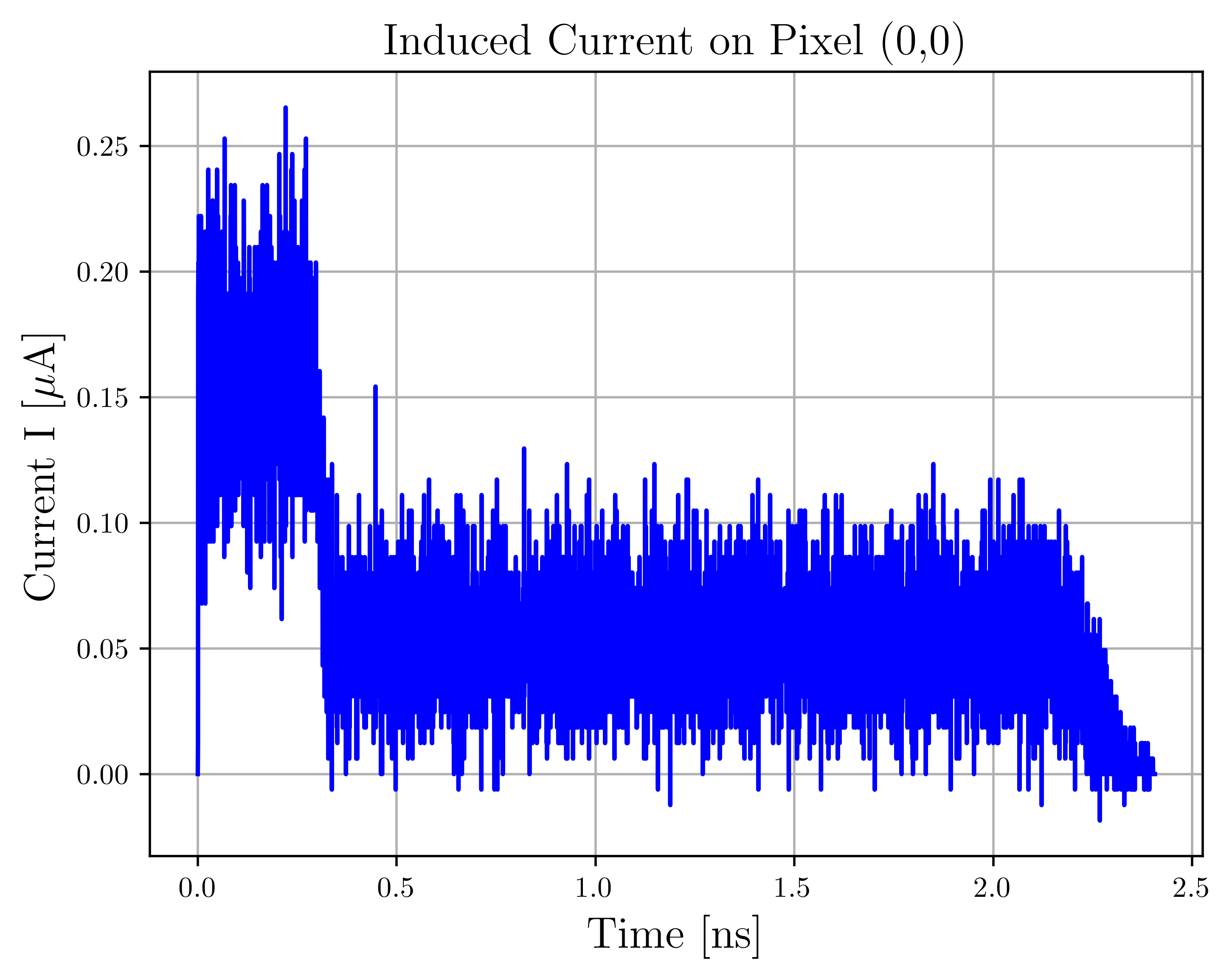
I had only one question with regards to this output, what is the source of the the jitter? I am attaching the relevant root file as well. modules.root (25.1 MB)
that indeed looks quite nice! The jitter is an artifact from the numerical integration I would say, and you could either average a few waveforms with the same initial charge deposition, or rebin the waveform to average out the bin-to-bin fluctuations.
[TransientPropagation]
temperature = 293K
charge_per_step = 1
timestep = 10ps
timestep_max = 10ps
induction_matrix = 1 1
mobility_model=“masetti_canali”
integration_time = 40ns
what is induction matrix exactly doing here? i can not see it in the manual