I seem to be having a problem with the DetectorHistogrammer module! Allpix^2 seems to work just fine, as every other module produces output that I can use. However, I find that although DH produces output, the histograms are empty! This seems a bit weird to me.
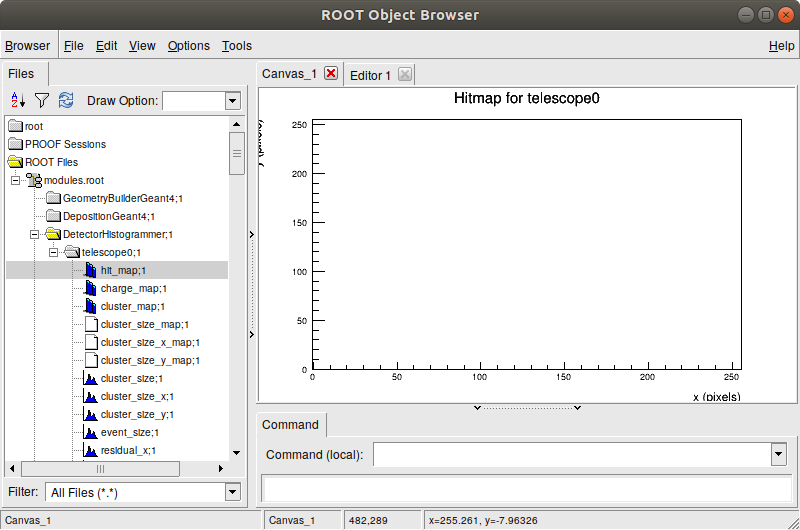
I have tested this with multiple configuration files, even with the examples that were provided with the framework. Just adding the DetectorHistogrammer module to the configuration file and setting output_plots = 1 gives me the .root file with the histograms in them, but they don’t actually show any data.
A figure for reference is given below.
Is this a familiar problem? Is there something that I need to check in my installation?
This may be a very broad question, and if it is, I apologise. Thank you in advance.
it matters where you place the module in your configuration file. Since it acts on PixelHit messages it has to be placed after the DefaultDigitzer module. Without this, the module will not receive any messages/input data and thus allocate the histograms but have nothing to fill them with. In your screenshot, it seems to be placed directly after the DepositionGeant4 module, where no digitized pixel hits are available yet.
As a general rule, place it just at the end of the configuration file.
If you like you can upload your configuration files here and I’ll have a look what’s wrong with them.
Thank you for the response! It definitely seems to work now. I actually realised that I now have another question; is it possible to produce this output data for more than one layer? Say that, for example, I would like the hitmap for a telescope layer and the dut, could I specify two “name” parameters in the configuration file? Or is there another way to create this data?
I initially posted this comment saying that I figured it out, but that appeared not to be the case. When I add the telescope planes under the parameter
name = “dut”, “telescope1”, … etc,
like in the SimpleTransfer module, I do get 3 separate folders in the TBrowser, but unfortunately every one of them but the dut one is empty. I seem to be doing it wrong; is there something in the allpix-manual that points to this or is there a neat little trick I can use?
with your configuration files available it would be quicker for me to spot the problem, but this is my guess based on what you describe:
The DetectorHistogrammer (such as also the SimpleTransfer you mentioned) is a “detector module” which only acts on a single detector. If you just place the module in the configuration file, without specifying name or type keywords, the framework will create one instance per detector:
[SimpleTransfer]
# Here you will only get one instance of the module, for the detector named "dut0"
name = "dut0"

[DetectorHistogrammer]
# Here you will get one instance PER DETECTOR available in your geometry file
For everything that goes beyond this, I would need to have a look at your configuration and geometry files.
I have only been carefully playing with the examples; I was just curious whether I could get some similar output to what Geant4 produces. I added the DetectorHistogrammer module to the Capacitive Transfer example, and now the conf file looks like this:
// set general settings
[Allpix]
log_level = “WARNING”
log_format = “SHORT”
detectors_file = “ccpd_example_detector.conf” # description of the detector placement
number_of_events = 100
experimental_multithreading = true
// create the detectors from the config and build the G4 model
[GeometryBuilderGeant4]
world_material = “air”
// use a single particle source, point it at the sensitive detector and start the beam
[DepositionGeant4]
physics_list = FTFP_BERT_EMZ # the physics list to use
particle_type = “e-” # the g4 particle
source_energy = 180GeV # the energy of the particle
source_position = 0um 0um -200000um # the position of the source
source_type = “beam”
beam_size = 6mm # gaussian sigma for the radius
beam_direction = 0 0 1 # the direction of the source
number_of_particles = 1 # the amount of particles in a single ‘event’
max_step_length = 20um # maximum length for a step in geant4
// read electric field
[ElectricFieldReader]
model = “linear”
bias_voltage = -6V
depletion_voltage = -3V
[DetectorHistogrammer]
name = “dut” <------------This is the part I’m curious about.
output_plots = 1
[RCEWriter]
Do you mean the “ccpd_example_detector.conf” file for the geometry file? This file specifies 7 planes, I was just wondering whether I could for example compare the hitmap in plane1 vs plane6.
The detector conf is given below.
[Plane1]
type = “ibl_planar”
position = 0 0 0
orientation = 0 0 0
[Plane2]
type = “ibl_planar”
position = 0 0 10
orientation = 0 0 0
[Plane3]
type = “ibl_planar”
position = 0 0 20
orientation = 0 0 0
[Plane4]
type = “ibl_planar”
position = 0 0 40
orientation = 0 0 0
[Plane5]
type = “ibl_planar”
position = 0 0 50
orientation = 0 0 0
[Plane6]
type = “ibl_planar”
position = 0 0 60
orientation = 0 0 0
[dut]
type = “ibl_planar”
position = 0 0 30
orientation = 0 0 0
Not providing these keywords will create one module per detector you have configured in your geometry.
Providing a (list of) name or type will instantiate the module only for these detectors
You can also combine this to.e.g change the electric field for one detector only:
# This is created for every detector:
[ElectricFieldReader]
model = "linear"
depletion_voltage = 30V
bias_voltage = 50V

# Now let's change the bias voltage only of Plane 2
# This definition takes precedence over the previously created due to the "name" keyword priority
[ElectricFieldReader]
model = "linear"
depletion_voltage = 30V
bias_voltage = 35V
Which means, in your example you would have to just remove the name keyword from the DetectorHistogrammer module to get instances for all detectors in your setup.
Edited the message because it does actually work! I’m gonna try to make my own configuration and see if it works as well as the example did. Thank you for the help. I will post a question here if I have any more.
I have configured my own detector setup with four layers, though what you suggested about removing the name parameter for DetectorHistogrammer unfortunately does not produce plots for every plane of the detector. My setup files can be found below: the sensor (model), the configuration of the simulation, and the spatial configuration of the four planes.
I’ve had a look at your configuration and have noticed a couple of issues:
In order to locate the detector model if you place it in the same folder, you could add the following key to your main setup file:
model_paths = ./
This means, you don’t have to place the sensor.conf file on the models directory but you can keep it with your configuration.
The file sensor.conf contains two sections commented as #Tungsten spacer 1, one of the sections is commented - but not its parameters. This means, they effectively overwrite the previous values:
[support]
position = "sensor"
position = "absolute"
results in position = "absolute". If you want to remove one, comment all lines.
The same problem appears in your 4_layer_setup.conf configuration file, here it looks like this:
[SimpleTransfer]
name = "Plane1", "Plane2", "Plane3", "dut"
#output_plots = 1

#[CapacitiveTransfer]
name = "dut"
This effectively translates to
[SimpleTransfer]
name = "dut"
which means, you are transferring only charge carriers for the detector dut from the sensor to the readout chip - which is why you only see results fro this detector. To fix this, consider using the [Ignore] keyword to switch off individual modules (see here in the manual).
which means that some of your detectors overlap. This usually results in missing tracking and energy deposition from Geant4, so be careful with the placement of your detectors.
Here is a version of your configuration files with above problems (except for the positioning) solved:
First of all, you’re a saint! Thank you for taking the time to find all these issues for me. A lot of these things arose from ignorance on my part, so my apologies. Everything seems to work as I wanted/expected it to now. Thanks again for the trouble!