Unexpected pulse signal of a CdTe detector

Hi everyone,

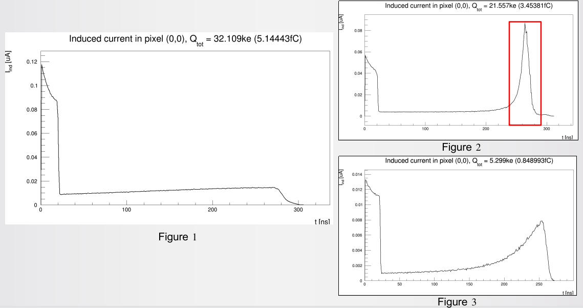
I am simulating the readout signal from the electrode after a gamma photon of a certain energy is incident on the CdTe detector. But to my surprise, the electrode signal from the center of the detector incidence does not appear to match the electrode signal from the edge incidence of the two detectors.
In my example, I expect to see a waveform in Figure 1 similar to the sum of Figure 2 and Figure 3 waveforms, but Figure 2 has a very high peak around 260ns, which is what I’m having trouble figuring out.

Thank you and best regards,

Eureka.

Configuration files are as follows.

[Allpix]
log_level = "INFO"
log_format = "DEFAULT"
detectors_file = "hpixla_v1a_detector_1000um_500um.conf"
number_of_events = 10

[GeometryBuilderGeant4]

[DepositionGeant4]
physics_list = FTFP_BERT
enable_pai=false
pai_model="pai"
particle_type = "gamma"
source_energy = 140keV
source_position = 0.7mm 5mm 0mm
source_type = "beam"
beam_size = 0.1um
beam_direction = 0 -1 0
number_of_particles = 1
max_step_length = 1um
fano_factor=0.10
charge_creation_energy=4.35eV

[ElectricFieldReader]
model = "constant"
bias_voltage=448V
#file_name="/run/media/allpix/D493-7F1F/tran/cdte_500um_1600um_3x3_320V_e_simplified_1_corrected3.init"
output_plots=false
[VisualizationGeant4]
mode = "gui"
[WeightingPotentialReader]
name="detector1","detector2"
model="pad"
output_plots=false
[TransientPropagation]
mobility_model = "custom"
mobility_function_electrons="[0]"
mobility_parameters_electrons=1050cm*cm/V/s
mobility_function_holes="[0]"
mobility_parameters_holes=80cm*cm/V/s
timestep=1ns
timestep_max=1ns
charge_per_step=50
integration_time=5us
output_plots=false
#trapping_model = "ljubljana"
#detrapping_model = "constant"
#detrapping_time_electron = 10us
#detrapping_time_hole = 50us
[PulseTransfer]
#output_plots=true
output_pulsegraphs=true

Dear @Eureka ,

thanks for your message. This is a bit difficult to diagnose for us as we do not know your sensor geometry. Could you maybe comment on that also? Also, could you comment on what is the difference between Figures 1, 2 and 3? In principle, signals are expected to differ between center and corner incidence, hence we’d need more details to spot any potential issues.

There are two points that I would like to comment on concerning your configuration file:

  • I recommend setting the random_seed parameter in the [Allpix] section to be able to reproduce results
  • The source is located at z=0mm and the beam is directed upwards. This is fine, as long as you make sure that your detector is not located accordingly.

Thanks and cheers
Paul