How is the local coordinate system in the geometry of the timepix on the chip board? The detectors have the origin at the lower left pixel, with the chipboard in the back and Z pointing towards us (away from the chip board). The chip board is a rectangle with the longer edges parallel to the Y axis and the longer part on negative X. Is it the same in Allpix2?
When there is no rotation, how is the local coordinate system oriented with respect to the global coordinate system? What rotations would be needed to have the local and the global coordinate systems pointing the same directions?
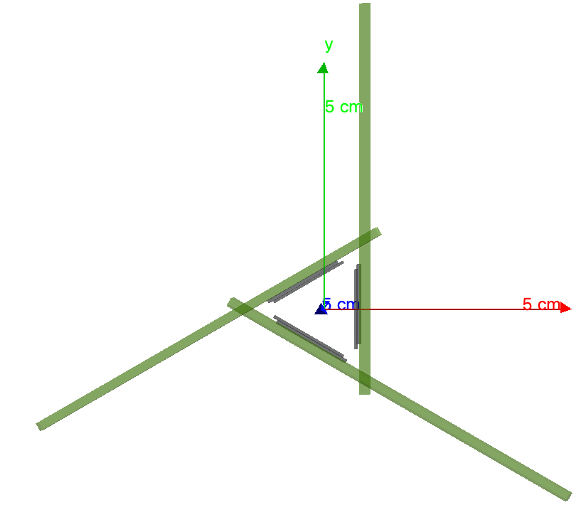
The global coordinate system is chosen as a right-handed Cartesian system, and the rotations of individual devices are performed around the geometric center of their sensor.
Local coordinate systems for the detectors are also right-handed Cartesian systems, with the x- and y-axes defining the sensor plane. The origin of this coordinate system is the center of the lower left pixel in the grid, i.e. the pixel with indices (0,0).
No, not really. The questions were too confusing. We have read many times that page of the manual and we couldn’t completely understand.
Let me rephrase it?
1 - With the local origin in the center of lower left pixel and at mid-depth in the sensor, does the z-axis points towards the chip or away from the chip?
2 - Without any rotation applied to the sensor, are the local axes pointing to the same directions as the global axes? If not, how are they oriented?
Sorry for that then - let me try to add the missing bits then:
the z axis points towards the sensor top surface, i.e. the side where the readout happens. For hybrids, this is the side where your ASIC is bumped to.
with no rotation applied, the z axis of the local and global coordinate are aligned.
I do not recommend looking at the visualization because the way things are rendered there can be very confusing and have lead myself down a wrong rabbit hole several times. Better to generate a known pencil beam and look at the hit map.
Hi @simonspa,
I’ve been together with @bali trying to get out of a huge gallery of holes
This was very useful. Everything is crystal clear now. Thank you very much.
Could you maybe come up with an improved formulation for the user manual? If possible for you a merge request would of course be great so I can attribute the improvements to you directly and list you as contributors.
The CI is stuck at the compilation and testing stages. Can you please have a look and let me know how to fix it. I didn’t add any runner in CI, so it’s the default one.
Here are the changes we made to the coordinate system section in Simulation Geometry
great to hear you managed to implement the changes - looking forward to merging them!
Concerning the CI, there are two issues I think:
Currently your repository is private, so I cannot see the pipeline status and/or code. Maybe consider making it public.
We use some private runners (mostly the Macs) for our CI pipeline to also test on macOS. I have just given you access to these runners. You need to activate them in the settings of your repository.
Would you mind opening a merge request already? Then we could continue technical details and code discussions directly there!