Hello everyone,
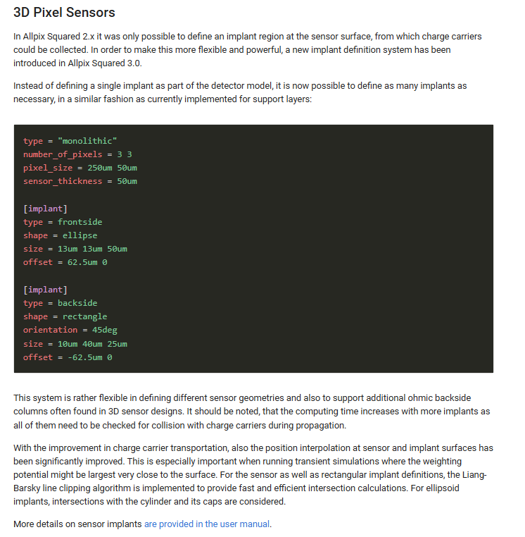
I am currently working on simulating 3D pixel sensors in Allpix Squared, specifically for use with the 3D53B chip.My goal is to make a realistic simulation of a 3D pixel sensor, and i am wondering if it is as simple as defining two implants as shown in this picture, or do i need to add more implants?
This is the model configuration i am currently using for RD53B (without any implants):
######################
SPDX-FileCopyrightText: 2021-2024 CERN and the Allpix Squared authors
SPDX-License-Identifier: MIT
type = “hybrid”
geometry = “pixel”
number_of_pixels = 400 384 #
pixel_size = 50um 50um
sensor_thickness = 150um
sensor_excess_top = 0.0mm
sensor_excess_bottom = 0.0mm
sensor_excess_right = 0.0um #0.6
sensor_excess_left = 0.0um #0.6
bump_sphere_radius = 9.0um
bump_cylinder_radius = 7.0um
bump_height = 20.0um
bump_offset = 0.0um 0.0um
chip_thickness = 400um
######################
Any help is appreciated!