Hello,
I am studying the effects of multiple scattering for different materials within the testbeam setup using the eudet_rd53a, which is an expansion of the eudet_telescope example.
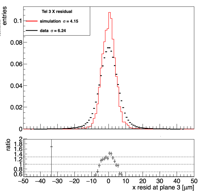
After reconstructing the simulated tracks for the telescope planes I compare them with testbeam data, some plots are shown below.
The simulation produces much smaller residuals than testbeam, I understand this can actually come from several reasons. But I’m not exactly sure what they are in the eudet_telescope example.
My questions are:
1- In the testbeam at DESY the setup includes two overlapped scintillators before and after the telescope planes, was this material included in allpix2? It is not in the geometry configuration but perhaps impeded somewhere else?
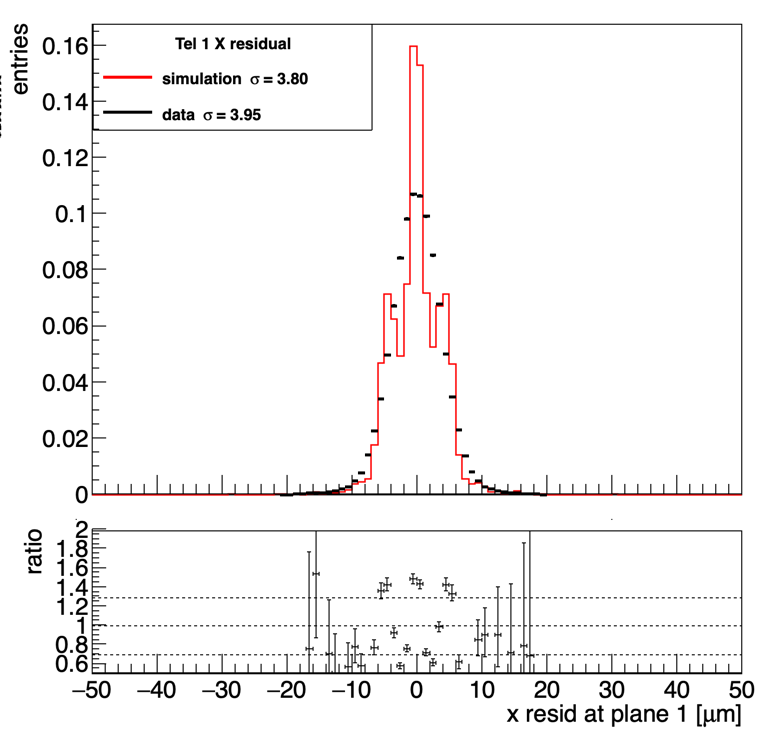
2- The residual produced from simulated tracks for planes 1 & 4, which are the middle of the triplet, have this 3 peaks Gaussian distribution (see plot Tel1), I dont suppose this is mapping something geometrical in the sensor. Have you seen this before?
Thank you very much!
Hi @retaibah
The scintillators are not included but also do not matter since they are outside of any planes and measurements and therefore cannot influence the track fitting result.
The reason both for the very narrow residuals as well as for the structure you see in the others most likely stems from the fact that you are not simulating any misalignment. You therefore get pixel-perfect overlaps in simulation which lead to odd artifacts. I would suggest using the alignment_precision_position and alignment_precision_orientation parameters to generate an arbitrary misalignment, and then perform the same alignment procedure to the simulation as you use for data.
Cheers,
Simon
Hi @simonspa,
I am actually trying to do the same thing as Reem, but for the analysis I am using Corryvreckan.
I did try with the misalignment in the detector configuration file for the simulation:
alignment_precision_position = 50um 50um 1mm
alignment_precision_orientation = 1deg 1deg 1deg
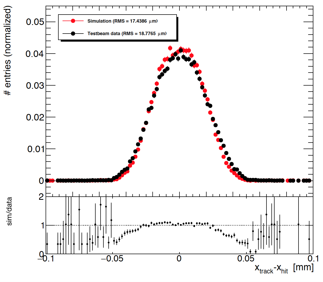
And I am sharing the residual width comparison between the simulated and test-beam data for one of the DUTs in the setup.
I am not sure how to further reduce the difference between the residual width. Are the misalignment values I tried too small? Do you think there is something else that is contributing to this difference in the residual width?
Thank you in advance for your help!
Šejla
Hi @sehadzic
I would argue that they match quite nicely already, and that remaining differences might as well be found in the data  For example there seem to be some sort of “bump” close to the tails which seem a bit odd and might be a bit of remaining misalignment in data of some sort.
Apart from that, I would suggest to
- cross-check that all scattering material between planes is included in the simulation (air, Kapton foils…)
- calculate what the theoretically expected residual width or resolution would be (e.g. using GitHub - simonspa/resolution-simulator: Schnitzelbroetchen mit Fisch)
- Finally this can of course also be a result of differences in the sensor simulation - if the simulated sensor has a better intrinsic resolution, we expect some deviation in the residual, too
Best,
Simon
Hi @simonspa,
thank you for your reply
For the material budget in Corryvreckan I used the value I get from the CorryvreckanWriter module in allpix-squared, but I don’t think the air is included in that value. I know that sensor thickness, chip thickness, bump bonds and any supports are included, but for air I am not sure. If I want to add air in the material budget, would that mean that for telescope plane 1 I add the value which corresponds to the air between telescope plane 0 and 1? And I repeat this for every plane in the setup?
The resolution-simulator looks very interesting, I was not aware of it before. I will try it out.
Thanks a lot,
Šejla
Hi @sehadzic
no, that’s not how it works. Volume scatterers need to be properly placed at certain distances between the planes, so this is something that Corryvreckan does for you.
Check out the [Tracking4D] module README and have a look at volume_scattering and volume_radiation_length. For air, basically simply set
[Tracking4D]
volume_scattering = true
and you’re done. It will add additional scatterers for air, placed at the correct positions between every plane of your setup.
/Simon
Hi @simonspa,
thanks a lot! I will try that out
Šejla