Mobility Calculation using AllPix's Electric Field

Hey everybody,

I’m looking to calculate the mobility of the particles I simulate in Allpix, in order to be able to sanity-check some values for the tangent of the Lorentz Angle that I’ve calculated.

To do this, I’m using the standard formula:

tan(\Theta_{\text{L}}) = r \mu B

where

\Theta_{\text{L}}” is the Lorentz Angle
“r” is the Hall Scattering Factor (set to one for my purposes)
\mu” is the mobility (that must be calculated, and depends on the electric field and temperature)
“B” is the magnetic field (which I set manually in my config file)

In order to calculate the mobility, I’m using a script from the radiation damage digitiser in athena. I don’t know if I’m allowed to post it here, but suffice it to say that I need to use the electric field strength as an input in the calculation. Right now I’m not sure how to go about this. I’m thinking of simply taking the value of the electric field at whatever depth my particles are deposited (I’m using DepositionPointCharge) and use that value to try and calculate the mobility. However, this means that I need some way to extra the electric field value at that point.

How can I do this? Right now, the limit of my knowledge is using mesh_plotter and ElectricFieldReader to plot the electric field (see attached photos). What do I need to do to extract the electric field strength at a specific coordinate?

Cheers,
Damir


Hi @damir

I am relatively sure posting links to the public Athena repo is perfectly fine :wink: Especially given its Apache 2.0 license.

Where would you like to extract the value from? Once you are running Allpix Squared or before, e.g. in the mesh plotter?

What these calculations usually take is the saturation velocity in your sensor. If you deposit a single blob of e/h pairs deep in your sensor with magnetic field and create linegraphs for an event, you will see that they will (given high enough bias) have a constant drift to the right, resulting in a straight line drift path. Only in this saturation regime you can actually calculate the Lorentz angle meaningfully.

/Simon

Hi @simonspa,

I am relatively sure posting links to the public Athena repo is perfectly fine :wink: Especially given its Apache 2.0 license.

I don’t think it’s on the athena public repo yet. It’s still a work in progress and it’s on the gitlab of one of my colleagues. I think I can post a few lines of code that use the electric field in calculation, however.

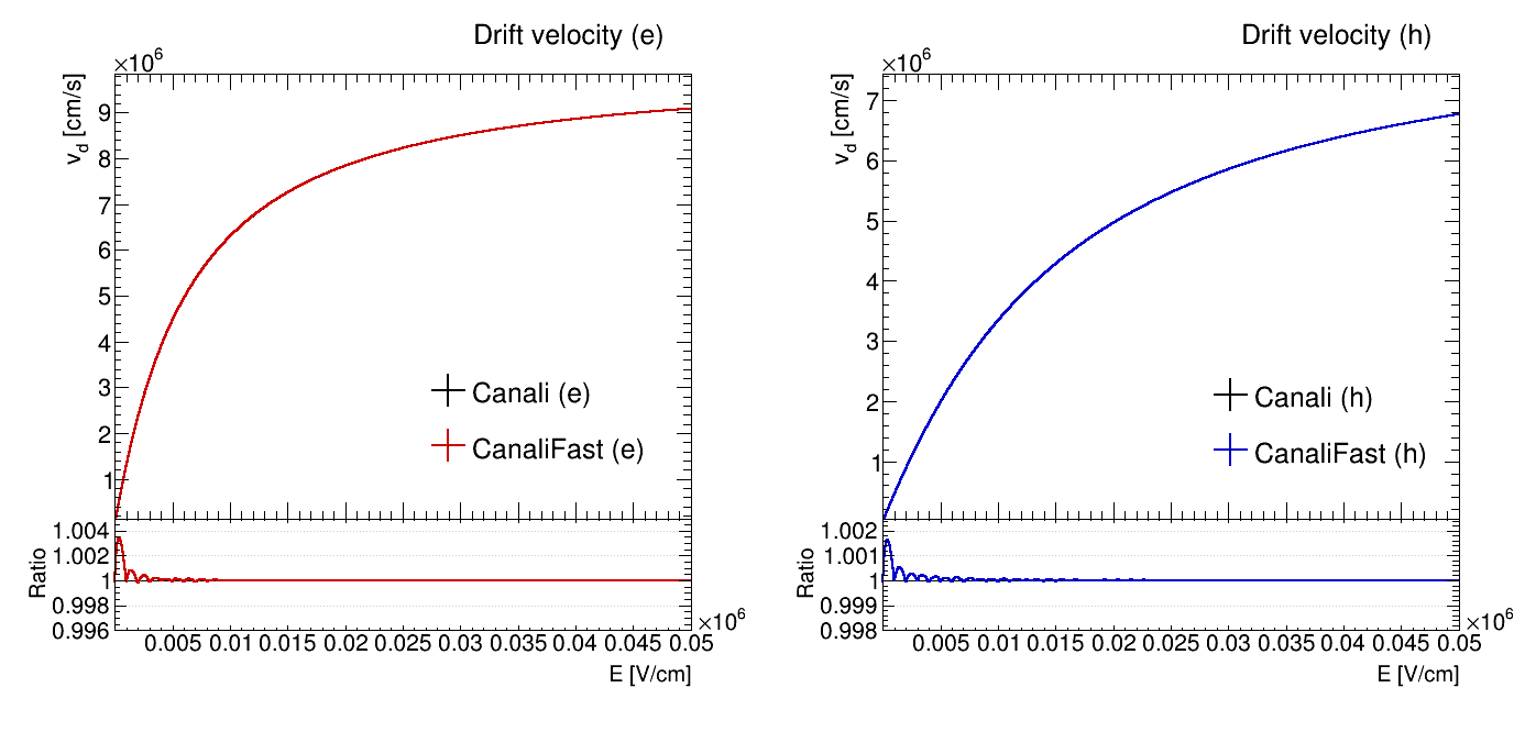
double num_e = vsat_e/ecrit_e;
double den_e = pow(1+pow((electricField/ecrit_e),beta_e),(1/beta_e));
double mobility_e = r_e*num_e/den_e;

double num_h = vsat_h/ecrit_h;
double den_h = pow(1+pow((electricField/ecrit_h),beta_h),(1/beta_h));
double mobility_h =  r_h*num_h/den_h;

Here, the “e” and “h” refer to quantities pertaining to electrons and holes, respectively. The “vsat” refers to (I think) the saturation velocity and “ecrit” refers to (again, I think) the critical temperature. Both “vsat” and “ecrit” depend solely on the temperature.

Where would you like to extract the value from? Once you are running Allpix Squared or before, e.g. in the mesh plotter?

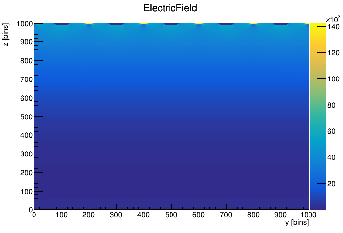
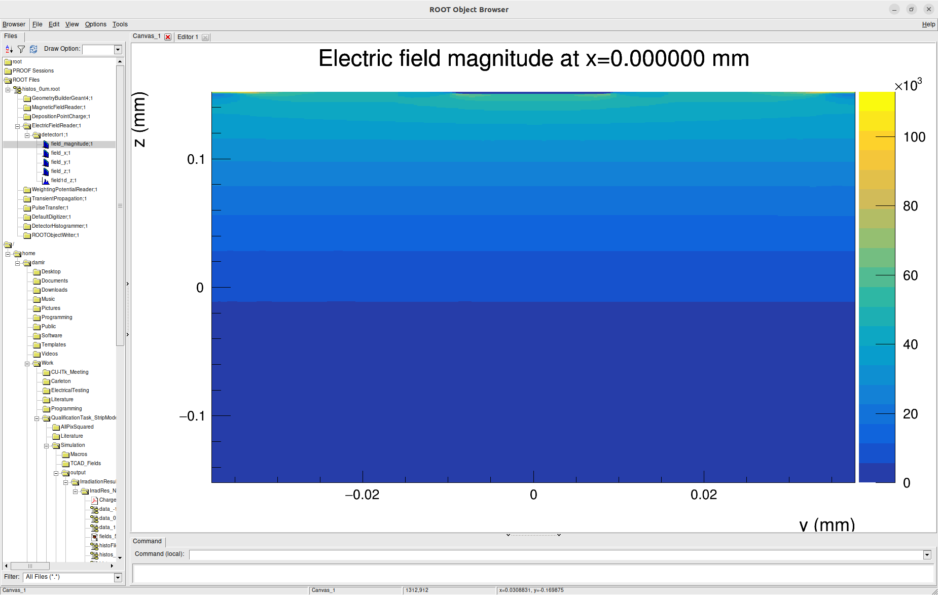
In order to calculate the mobility, I only really need a single value of the electric field (which I think is taken from the position that the charges are deposited). I was thinking that I would extract them from the histogram file that allpix generates, the one that contains all the modules as directories:

histos_FileStructure

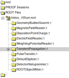
How can I extract the value of the electric field from this file? I’m assuming I’ll probably have to write a ROOT macro like I’ve done to calculate things like the charge collection efficiency or the tangent of the Lorentz Angle.

Sidenote: I don’t know what the technical name for the output files of allpix are. I’ve been calling the above file the “histogram file” (while it’s variable name is “root_file”) and the other file the “data file” (which contains the trees used to calculate things like charge collection efficiency, but only uses “file_name” in the config file), but these are just what I use.

As for your final point:

What these calculations usually take is the saturation velocity in your sensor. If you deposit a single blob of e/h pairs deep in your sensor with magnetic field and create linegraphs for an event, you will see that they will (given high enough bias) have a constant drift to the right, resulting in a straight line drift path. Only in this saturation regime you can actually calculate the Lorentz angle meaningfully.

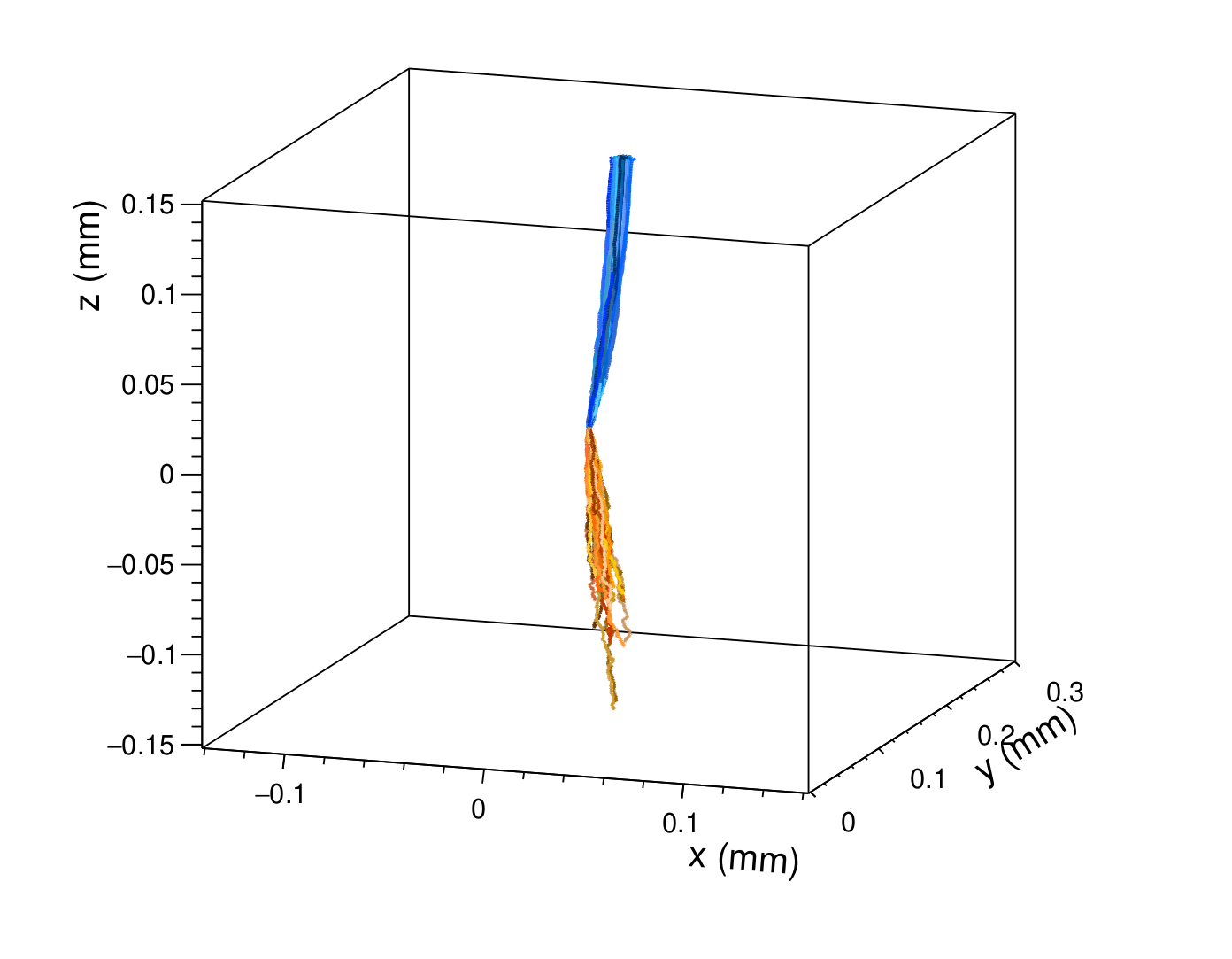
This makes sense. I’ve been working with a non-zero magnetic field the whole time I was working with Allpix, so the deflection thing is known to me. I’ve recently begun using an electric field that includes modelling for radiation damage and traps, so my particle drifts looks different as well.

This angle isn’t the best, but the electrons seem to curve as they head towards the electrode at z=0.15mm.

Cheers,
Damir

Hi @damir

I’m pretty sure you can, this is the standard mobility formula following e.g. the Canali model which you can also find in our handbook.

The formulae even state vsat_e, referring to the saturation velocity, as you state. ecrit is the critical electric field, just another fitting patrameter for the model, not free parameters. Have a read at the link posted above, our manual is quite verbose on the models and also links all relevant literature (i.e. their origin).

Extracting the value of a single bin in a histogram in ROOT is quite straight forward. However, since we use the same formula to describe the mobility during the drift of the charge carriers, I cannot follow what your actual goal here is.

Best regards,
Simon

Hi @simonspa

Extracting the value of a single bin in a histogram in ROOT is quite straight forward. However, since we use the same formula to describe the mobility during the drift of the charge carriers, I cannot follow what your actual goal here is.

My goal is to just calculate the tangent of the Lorentz Angle using an alternate method as a sanity check to make sure my simulations are correct. So far, I’ve been calculating the tangent of the Lorentz Angle using the displacements in x and z that the particles I deposit into the sensor undergo. The algorithm is something like this:

  • Deposit 1000 particles at some (x,y,z) coordinate
  • Allow them to propagate for 25ns under electric and magnetic fields
  • Use their final locations to calculate their displacements in x (\Delta x) and z (\Delta z)
  • Make a scatter plot of these values and fit them with a straight line
  • tan(\Theta_{\text{L}}) is then the slope of the fit line

I want to check this method by using the formula in the OP. To do this I just need to extract the value of the electric field. If I understand you correctly, the electric field is stored in the allpix output as a TH2? Can I ask how the modules are handled in this file? As far as I know they aren’t ROOT branches, but I don’t know any other way that ROOT can store information.

I’m pretty sure you can, this is the standard mobility formula following e.g. the Canali model which you can also find in our handbook.

The formulae even state vsat_e, referring to the saturation velocity, as you state. ecrit is the critical electric field, just another fitting patrameter for the model, not free parameters. Have a read at the link posted above, our manual is quite verbose on the models and also links all relevant literature (i.e. their origin).

I have a passing familiarity with the mobility models used in allpix, although I was introduced to them in the context of the athena script I mentioned (in particular, we talked a bit about the 1.43 coefficient that the Jacoboni Model seemed to have been a typo).

Now that we’re on the topic, is there any way to just have allpix output the mobility manually? Since Allpix seems to calculate everything anyway, is there a way to output the mobility at different points in the sensor like we do for the electric field? Maybe a plot of some kind?

Also, I was reading through the TransientPropagation module yesterday, and I noticed that there’s an option called output_linegraphs_trapped. Apparently, without it explicitly set to true any particles that become trapped don’t have their linegraphs plotted?

Cheers,
Damir

Hi @damir ,

Indeed, in this “modules” file, the histograms are stored directly, just in a file structure. So, you can extract them from there and then do whatever you wish with them. So, as an example doing this in the interactive ROOT prompt, having done root -l modules.root, we can do

root [1] auto histo = _file0->Get("ElectricFieldReader/dut/field_magnitude");
root [2] new TCanvas
(TCanvas *) 0x555c68396380
root [3] histo->Draw()

to draw the field magnitude histogram. Note that this histogram is only in the selected “slice” however, defaulting to the centre of the pixel.
From this, you could also easily get the value of a certain bin in the histogram. You could also use FindBin() of the axes to find the bin closest to a given position.

If you wish to make a histogram of the mobility values, you can do so by adding one in the code of the propagation module. If you look around in the code a bit, it should become quite clear how to create a histogram there. My tip would be to pick one that exists, find all occurrences of its name, and just make sure your new one does all the same things.

As for your last point, this is not exactly true. If output_linegraphs_trapped is false, they will still be included in the first linegraph, which contains all charge carriers in the event. If you do set it to true, you get a separate linegraph containing just the paths of the trapped charge carriers.

Kind regards,
Håkan