For the moment, I am studying the detector response using the linear electric field approximation. In this model, either you set the bias voltage and the depletion depth or you set the bias voltage and the depletion voltage.
But in the case where the depletion voltage is not given in the config file, the depletion voltage will be set to be equal to the bias voltage. When the bias voltage is negative, this results in a zero electric field at the front side of the detector, and so this affects the charge collection at the very beginning when a low energy particle interacts with the detector volume.
Is this normal? Why have you chosen to do this? can this be fixed in the future to allow the calculation of the full depletion voltage from the depletion depth, in case the depletion voltage is not given?
may I ask which kind of sensor you are trying to simulate?
The behaviour you describe is indeed intended. The depletion characteristics of your sensor depend strongly on the design of your sensor. The parameters depletion_depth and depletion_voltage are two attempts to boil down these information to what we need for modeling the electric field.
As we can’t know the properties of your sensor, we have to use these as a best guess. If no depletion_voltage or depletion_depth is given, our best guess is to say, the bias_voltage is just enough to deplete your sensor, which results in the linear function going down to 0 at one side of the sensor. At which side the field goes down to 0 can be controlled using the deplete_from_implants parameter. You can set it to false, if you e.g. simulate n-in-n sensors.
In order to create an electric field that does not go down to 0, you need to go to overdepletion. For this you need to state the depletion_voltage in addition to the bias_voltage, where bias_voltage > depletion_voltage.
The depletion_depth can only be used for sensors biased below depletion and will build up an electric field that shows a linear dependency on the depth, going down to 0 at the depletion_depth.
I hope this could clarify the situation. Please don’t to ask any follow-up questions!
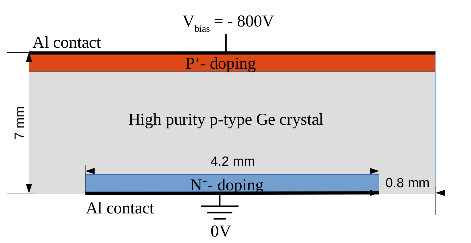
The detector I am simulating for the moment is an n-in-p sensor, depletion voltage -550V, the bias voltage is -800V, see the schematic figure attached. The top side (P+ doped layer) should be the front side facing the beam (coming along the z-axis).
Up to now, I used the bias voltage and the depletion voltage parameter cited above but the deplete_from_implant parameter is true by default, which makes the electric field point toward the backside which is the inverse of I should have for my case. Where is the bias voltage supposed to be applied? On the front side, I guess?
all that depends a lot on the definition of front side and back side. Usually the front side is where the implant is, which for you would mean the n+ doped side. It is defined at the positive side in z in local coordinates.
Hence, my advice for you would be to apply an electric field defined as follows:
[ElectricFieldReader]
model = "linear"
voltage = -800V
depletion_voltage = -550V
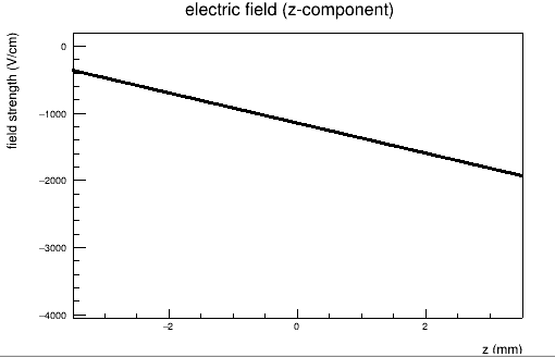
Now, with this, you will get an electric field shaped just like in the attached image:
Again, this is in local coordinates. Hence, the electric field has its highest amplitude at the front side, which is what you would expect. Furthermore, the detector is fully depleted, as you went above the depletion voltage of -550 V.
This should be clarified then as well? The above plot indicates the electric field to point towards the back side, which is per definition the side with the p+ doping and with the voltage applied.
Maybe also this is the confusing part: What we call the front side is a sensor-specific term and doesn’t refer to the beam at all. But as the front side is at positive coordinates along z and the beam is (per default) pointing towards positive z, the back side is traversed first by the particles, if you do not rotate the sensor.
So for me it actually seems like you’re doing the right thing. Did the clarification of definitions help?
Allow me one last remark: Allpix Squared is dedicated to the simulation of silicon detectors. From the image you attached it seems like you are simulating germanium? Be aware that at several positions in the source code assumptions are made that apply to silicon only, so the simulations might not represent measurements adequately.
