Dear developers,
I met a problem when converting ElectricField from TDR files.
The command line I used is:
mesh_converter -c converter.conf -f n2_des
The configuration file is:
model=‘apf’
dimension=2
region=‘Silicon_1’
observable=‘ElectricField’
xyz=z y x
initial_radius=0.01um
max_radius=200um
There is a fatal error:
|13:01:45.187| (STATUS) Welcome to the Mesh Converter Tool of Allpix^2 v1.6.0
|13:01:45.187| (STATUS) Using converter.conf configuration file
|13:01:45.187| (STATUS) Reading mesh grid from file “n2_des.grd”
|13:01:45.283| (INFO) Parsing grid file: done.
|13:01:45.290| (INFO) Grid sizes for all regions:
|13:01:45.290| (INFO) Aluminum_1 744
|13:01:45.290| (INFO) Aluminum_1+Gas_1 106
|13:01:45.290| (INFO) Aluminum_1+Silicon_1 142
|13:01:45.290| (INFO) Aluminum_2 213
|13:01:45.290| (INFO) Aluminum_2+BackMat_1 95
|13:01:45.290| (INFO) Aluminum_2+Silicon_1 81
|13:01:45.290| (INFO) BackMat_1 142
|13:01:45.290| (INFO) Gas_1 1294
|13:01:45.290| (INFO) Gas_1+Silicon_1 168
|13:01:45.290| (INFO) Silicon_1 17237
|13:01:45.290| (INFO) anode4 95
|13:01:45.290| (INFO) cathode 95
|13:01:45.290| (STATUS) Reading field from file “n2_des.dat”
|13:01:45.442| (INFO) Parsing field data file: done.
|13:01:45.442| (INFO) Field sizes for all regions and observables:
|13:01:45.442| (INFO) Aluminum_1:
|13:01:45.442| (INFO) ElectricField 744
|13:01:45.442| (INFO) ElectrostaticPotential 744
|13:01:45.442| (INFO) Aluminum_2:
|13:01:45.442| (INFO) ElectricField 213
|13:01:45.442| (INFO) ElectrostaticPotential 213
|13:01:45.442| (INFO) BackMat_1:
|13:01:45.442| (INFO) ElectricField 142
|13:01:45.442| (INFO) ElectrostaticPotential 142
|13:01:45.442| (INFO) Gas_1:
|13:01:45.442| (INFO) ElectricField 1294
|13:01:45.442| (INFO) ElectrostaticPotential 1294
|13:01:45.442| (INFO) Silicon_1:
|13:01:45.442| (INFO) AcceptorConcentration 17237
|13:01:45.442| (INFO) DonorConcentration 17237
|13:01:45.442| (INFO) DopingConcentration 17237
|13:01:45.442| (INFO) ElectricField 17237
|13:01:45.442| (INFO) ElectrostaticPotential 17237
|13:01:45.443| (INFO) Using initial neighbor search radius of 1e-05
|13:01:45.443| (STATUS) TCAD mesh (x,y,z) coords. transformation into: (z,y,x)
|13:01:45.443| (STATUS) Mesh dimensions: 1 x 200 x 1
New mesh element dimension: 1 x 2 x 0.01 ==> Volume = 0.02
|13:01:45.443| (INFO) Reading the files took 0 seconds.
|13:01:45.443| (STATUS) Starting regular grid interpolation with 6 threads.
|13:04:13.703| (FATAL) Fatal internal error
Could not find valid volume element. Consider to increase max_radius to include more mesh points in the search
Cannot continue.
The size of my mesh is 200um. When i use a larger max_radius, the problem can’t be solved
Best regards
When I use DEBUG level:
mesh_converter -c converter.conf -f n2_des -v DEBUG
There is part of output:
|13:56:59.213| (DEBUG) No (new) neighbour found with radius 0.19841. Increasing search radius.
|13:56:59.213| (DEBUG) Search radius: 0.19851
|13:56:59.213| (DEBUG) Number of vertices found: 0
|13:56:59.213| (DEBUG) No (new) neighbour found with radius 0.19851. Increasing search radius.
|13:56:59.213| (DEBUG) Search radius: 0.19861
|13:56:59.213| (DEBUG) Number of vertices found: 0
|13:56:59.213| (DEBUG) No (new) neighbour found with radius 0.19861. Increasing search radius.
|13:56:59.213| (DEBUG) Search radius: 0.19871
|13:56:59.213| (DEBUG) Number of vertices found: 0
|13:56:59.213| (DEBUG) No (new) neighbour found with radius 0.19871. Increasing search radius.
|13:56:59.213| (DEBUG) Search radius: 0.19881
|13:56:59.213| (DEBUG) Number of vertices found: 0
|13:56:59.213| (DEBUG) No (new) neighbour found with radius 0.19881. Increasing search radius.
|13:56:59.213| (DEBUG) Search radius: 0.19891
|13:56:59.213| (DEBUG) Number of vertices found: 0
|13:56:59.213| (DEBUG) No (new) neighbour found with radius 0.19891. Increasing search radius.
|13:56:59.213| (DEBUG) Search radius: 0.19901
|13:56:59.213| (DEBUG) Number of vertices found: 0
|13:56:59.213| (DEBUG) No (new) neighbour found with radius 0.19901. Increasing search radius.
|13:56:59.213| (DEBUG) Search radius: 0.19911
|13:56:59.213| (DEBUG) Number of vertices found: 0
|13:56:59.213| (DEBUG) No (new) neighbour found with radius 0.19911. Increasing search radius.
|13:56:59.213| (DEBUG) Search radius: 0.19921
|13:56:59.213| (DEBUG) Number of vertices found: 0
|13:56:59.213| (DEBUG) No (new) neighbour found with radius 0.19921. Increasing search radius.
|13:56:59.213| (DEBUG) Search radius: 0.19931
|13:56:59.213| (DEBUG) Number of vertices found: 0
|13:56:59.213| (DEBUG) No (new) neighbour found with radius 0.19931. Increasing search radius.
|13:56:59.213| (DEBUG) Search radius: 0.19941
|13:56:59.213| (DEBUG) Number of vertices found: 0
|13:56:59.213| (DEBUG) No (new) neighbour found with radius 0.19941. Increasing search radius.
|13:56:59.213| (DEBUG) Search radius: 0.19951
|13:56:59.213| (DEBUG) Number of vertices found: 0
|13:56:59.213| (DEBUG) No (new) neighbour found with radius 0.19951. Increasing search radius.
|13:56:59.213| (DEBUG) Search radius: 0.19961
|13:56:59.213| (DEBUG) Number of vertices found: 0
|13:56:59.213| (DEBUG) No (new) neighbour found with radius 0.19961. Increasing search radius.
|13:56:59.213| (DEBUG) Search radius: 0.19971
|13:56:59.213| (DEBUG) Number of vertices found: 0
|13:56:59.213| (DEBUG) No (new) neighbour found with radius 0.19971. Increasing search radius.
|13:56:59.213| (DEBUG) Search radius: 0.19981
|13:56:59.213| (DEBUG) Number of vertices found: 0
|13:56:59.213| (DEBUG) No (new) neighbour found with radius 0.19981. Increasing search radius.
|13:56:59.213| (DEBUG) Search radius: 0.19991
|13:56:59.213| (DEBUG) Number of vertices found: 0
|13:56:59.213| (DEBUG) No (new) neighbour found with radius 0.19991. Increasing search radius.
|13:56:59.213| (FATAL) Fatal internal error
Could not find valid volume element. Consider to increase max_radius to include more mesh points in the search
Cannot continue.
My grid files aren’t empty, but it can’t search for a vertice
Hi @Ricardo
when you say
The size of my mesh is 200um.
you mean that the input mesh has vertices with a distance of 200um and more? That seems quite large. If this is really the case, please try to increase your initial_radius because it currently is at 10nm and the algorithm might abort before it finds any useful volume.
Best,
Simon
Dear @simonspa :
Sorry to make you misunderstand.
I mean the total size of mesh is about 200um. The distance between mesh is from 0.1um to 1um.
Best regards
There is part of my dat file:
Dataset (“ElectricField”) {
function = ElectricField
type = vector
dimension = 2
location = vertex
validity = [ “Silicon_1” ]
Values (34474) {
-3.290570601245161e-06 -2.402111336099566e+02 -3.938213567771941e-06 -2.402111336099082e+02 -4.587007623022836e-06 -2.402111336098989e+02 -5.236330777684034e-06 -2.402111336099033e+02 -5.885716402144541e-06 -2.402111336099022e+02
-6.534618691108981e-06 -2.402111336099150e+02 -7.182433801222199e-06 -2.402111336099428e+02 -7.828592876986798e-06 -2.402111336099619e+02 -8.472799115625932e-06 -2.402111336100028e+02 -9.114813386280389e-06 -2.402111336100390e+02
-9.754613789388891e-06 -2.402111336100775e+02 -1.033465231624504e-05 -2.402111336112280e+02 -1.091234556718508e-05 -2.402111336100693e+02 -1.144681473827950e-05 -2.402111336100430e+02 -1.198265210106219e-05 -2.402111336099986e+02
-1.251986992984377e-05 -2.402111336099751e+02 -1.305844683372893e-05 -2.402111336099526e+02 -1.359812865589699e-05 -2.402111336099460e+02 -1.413847346036331e-05 -2.402111336099314e+02 -1.467908410256243e-05 -2.402111336099337e+02
-1.521993836231642e-05 -2.402111336099394e+02 -1.576086992691311e-05 -2.402111336099145e+02 -1.630143366947118e-05 -2.402111336099284e+02 -1.684110585444901e-05 -2.402111336099561e+02 -1.737961108616601e-05 -2.402111336099817e+02
-1.791667843785579e-05 -2.402111336100007e+02 -1.845205120771990e-05 -2.402111336100399e+02 -1.917858016904279e-05 -2.402111336071711e+02 -1.992784430048293e-05 -2.402111336100887e+02 -2.082425574836754e-05 -2.402111336100686e+02
-2.172278052630815e-05 -2.402111336100177e+02 -2.262241871718867e-05 -2.402111336100250e+02 -2.352253511956593e-05 -2.402111336100291e+02 -2.442221521586130e-05 -2.402111336100191e+02 -2.532055696210850e-05 -2.402111336100493e+02
-2.613585252531346e-05 -2.402111336112007e+02 -2.694774728298943e-05 -2.402111336100531e+02 -2.769840558616675e-05 -2.402111336100426e+02 -2.844998453694895e-05 -2.402111336100063e+02 -2.920202224317797e-05 -2.402111336100330e+02
-2.995417721621660e-05 -2.402111336100099e+02 -3.070594326015821e-05 -2.402111336100253e+02 -3.145684734622345e-05 -2.402111336100361e+02 -3.213858610523360e-05 -2.402111336111859e+02 -3.281754083313095e-05 -2.402111336100370e+02
-3.344500634109493e-05 -2.402111336100215e+02 -3.407297976014876e-05 -2.402111336100054e+02 -3.470122437591807e-05 -2.402111336100077e+02 -3.532954258132790e-05 -2.402111336100320e+02 -3.595765084509533e-05 -2.402111336100026e+02
-3.658530221244825e-05 -2.402111336099945e+02 -3.715533025407378e-05 -2.402111336110677e+02 -3.772320357816856e-05 -2.402111336098261e+02 -3.824790256765994e-05 -2.402111336096154e+02 -3.877286531639298e-05 -2.402111336091417e+02
Hi @Ricardo
hm, then I don’t see any obvious problem anymore. Would it be possible to make your mesh files available to me so I can have a look and see where things go wrong?
Best,
/Simon
Hi @simonspa
Thanks for your help!
I have solved the problem of not finding vertice by changing
max_radius=200um
to
max_radius=200
Is there any difference between the unit in configuration file and the unit in mesh file?
However, there is still a problem.
After a long time processing, the number of vertices found become a constant. When the radius reaches radius_max, there comes an error:
Could not find valid volume element. Consider to increase max_radius to include more mesh points in the search
it seems that there is something wrong with the edge of my mesh.
I generate the grd file and dat file through:
tdx -dd
The following is my grd file:
n2_des.conf (1.9 MB)
n14_des.conf (450.7 KB)
The former is a large structure and is time-consuming.
The latter is a small one I use to test. Both of them meet the same problem
In addition, I wonder what the meaning of radius_max is. Where is the center of radius in the mesh?
Best regards.
The dat file for the latter one is
n14_des.conf (2.5 MB)
Hi @Ricardo
oh, wow, that indeed is a bug. It seems like we are not properly treating units yet in the mesh converter - meaning your 200um are int5ernally converted to 0.2mm but then used as if it were 02.um.  Definitely something we need to fix, there should not be a difference in unit treatment!
Concerning the other issue I’ll have a look - thanks for adding your files!
Best,
Simon
Hi @Ricardo
I tried to convert your small example file and for me it worked without issue, see result below. Here is the converter configuration I have used:
model = apf

dimension = 2
region = "Silicon_1"

observable = "ElectricField"
xyz = x y -z
So my follow-up questions would be:
- Did you use a different configuration? The one from your initial post? For me also that works, even though you have to swap the axes to match the Allpix Squared coordinate system.
- What version of the MeshConverter (so: Allpix Squared) do you use?
Best
/Simon
Dear @simonspa :
Thanks for your reply.
It also works for me using your configuration file. However, when I change
xyz= x y -z
to
xyz= z y x
I meet the problem described before:
in TRACE mode, part of the output is:
|15:02:03.552| (TRACE) Invalid tetrahedron with coplanar(3D)/colinear(2D) vertices.
|15:02:03.552| (TRACE) Constructing element with dim 2 at (-1,68.4,-0.995)
|15:02:03.543| (TRACE) Invalid tetrahedron with coplanar(3D)/colinear(2D) vertices.
|15:02:03.552| (TRACE) Constructing element with dim 2 at (-1,38,-0.995)
|15:02:03.552| (TRACE) Invalid tetrahedron with coplanar(3D)/colinear(2D) vertices.
|15:02:03.552| (TRACE) Constructing element with dim 2 at (-1,38,-0.995)
|15:02:03.543| (TRACE) Constructing element with dim 2 at (-1,47.6,-0.995)
|15:02:03.543| (TRACE) Invalid tetrahedron with coplanar(3D)/colinear(2D) vertices.
|15:02:03.552| (TRACE) Constructing element with dim 2 at (-1,72.4,-0.995)
|15:02:03.535| (TRACE) Invalid tetrahedron with coplanar(3D)/colinear(2D) vertices.
|15:02:03.553| (TRACE) Constructing element with dim 2 at (-1,9.2,-0.995)
|15:02:03.553| (TRACE) Invalid tetrahedron with coplanar(3D)/colinear(2D) vertices.
|15:02:03.544| (TRACE) Invalid tetrahedron with coplanar(3D)/colinear(2D) vertices.
|15:02:03.553| (TRACE) Constructing element with dim 2 at (-1,26.8,-0.995)
|15:02:03.553| (TRACE) Invalid tetrahedron with coplanar(3D)/colinear(2D) vertices.
|15:02:03.518| (TRACE) Constructing element with dim 2 at (-1,75.6,-0.995)
|15:02:03.544| (TRACE) Invalid tetrahedron with coplanar(3D)/colinear(2D) vertices.
|15:02:03.553| (TRACE) Invalid tetrahedron with coplanar(3D)/colinear(2D) vertices.
|15:02:03.535| (TRACE) Constructing element with dim 2 at (-1,30,-0.995)
|15:02:03.544| (TRACE) Constructing element with dim 2 at (-1,73.2,-0.995)
In addition, in my TCAD files, the electric field is in xy plane. The manual says that in 2D conversion, the x axis will be set to 1. However, you use
xyz= x y -z
didn’t convert the axis. Have I understood something wrong?
At last, the version I use is 1.6.0. Both on my local computer and no CVMFS, I met the same issue.
Best.
Hi @Ricardo
indeed when swapping the axes I can also reproduce the issue, seems like I need to investigate this.
The reason for the mismatch of coordinate systems seems to be more of a documentation nature though. When I read through the DF-ISE files you provided it seems like TCAD simply sets dimensions = 2 and exports the data - but there is no information on whether these are x, y or z. So I think our manual should actually more precisely say something like:
Two-dimensional grids are always mapped into the yz plane and the x coordinate is set to zero.
Does that make sense?
Best,
Simon
Dear @simonspa 
Thanks for your explanation. Now, I understand it.
There is one last problem about mesh_plotter:
I have get the n14_des_ElectricField.apf file, and it’s not empty.
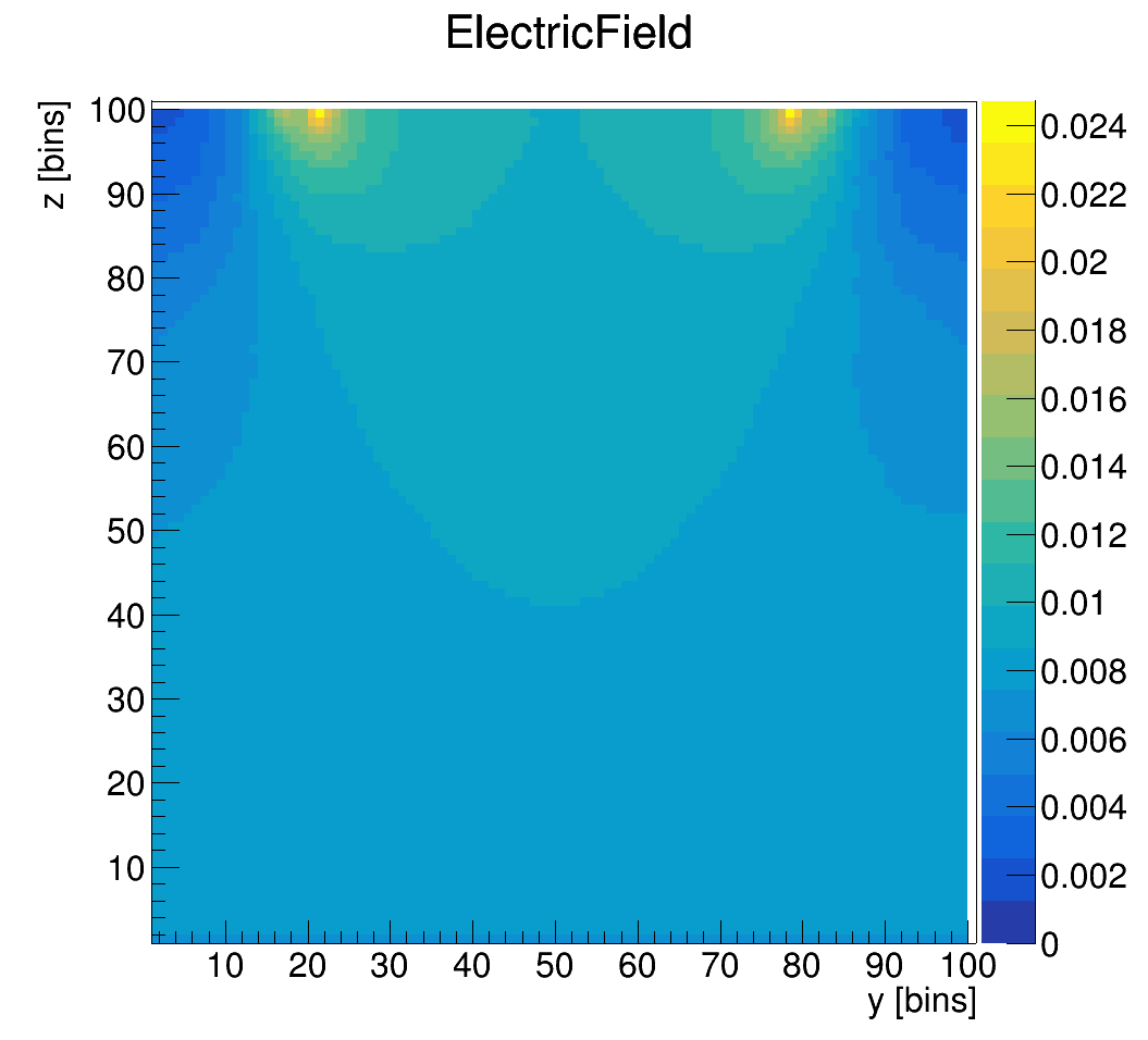
When I use mesh_plotter:
mesh_plotter -f n14_des_ElectricField.apf -p zy
I output a png like this
In xy plane:
How can I change the bin in the axis to get a figure like you upload?
In addition, when I use:
mesh_plotter -f n14_des_ElectricField.apf -p yz
There is an error:
(FATAL) Failed to plot mesh:
vector::_M_range_check: __n (which is 30000) >= this->size() (which is 30000)
I just change the sequence of yz.
Hi @Ricardo
yes, that’s indeed what I also ran into when plotting your field… 
Here is the fix: MeshPlotter: do correct slicing for 2D fields and add axis titles (!490) · Merge Requests · Allpix Squared / Allpix Squared
Alternatively, just run Allpix Squared itself with
[ElectricFieldReader]
output_plots = true
since it will also create these plots for you.
Best,
/Simon