Dear experts,
I am running allpix2 simulation for jadepix sensor. There is something wrong with the induced current plots. I have tried some mothods, but nothing changes. I don’t know what’s wrong with my setups. I will appreciate it if you can give some advice. Thanks in advance.
epi_1k_ElectricField.apf (22.9 MB)
jadepix_telescope.conf (1.8 KB)
jadepix3.conf (915 Bytes)
model_weightingpotential.apf (8.4 MB)
telescope1.conf (155 Bytes)
modules.root (78.1 MB)
Hi @zhiliang
looking at your electric field, only the top 5um of your sensor seem to contain a field. That means charge carrier motion in the rest of the volume will be dominated by diffusion, leading to a net-zero induced current.
I would expect that this part represents a substrate volume with high doping concentration, please consider adding a recombination model to properly describe this part of the sensor.
Also, I can recommend using line graphs to visualize what’s happening in your sensor, you can switch them on for your TransientPropagation module.
Best,
Simon
Hi, @simonspa
Thanks for your reply.
Yeah, I also study TransientPropagation and PulseTransfer modules these days and get interesting results.
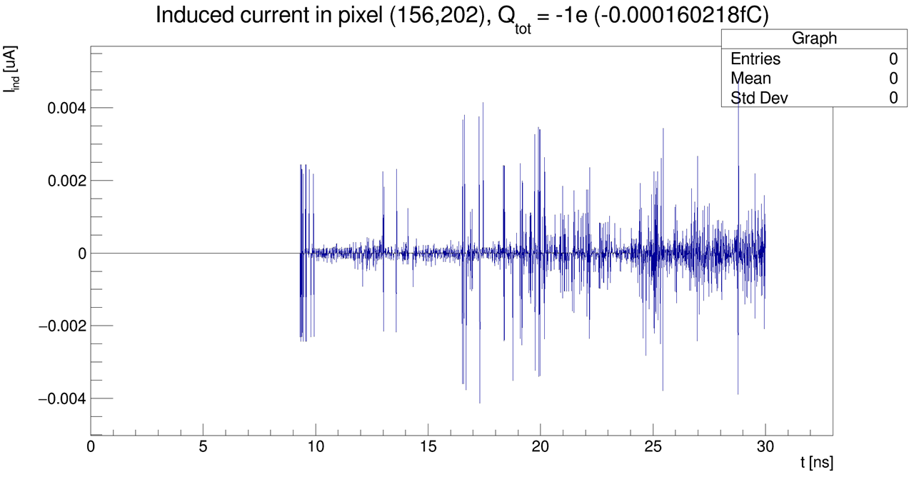
This graph is one event pulse, indicting nothing.
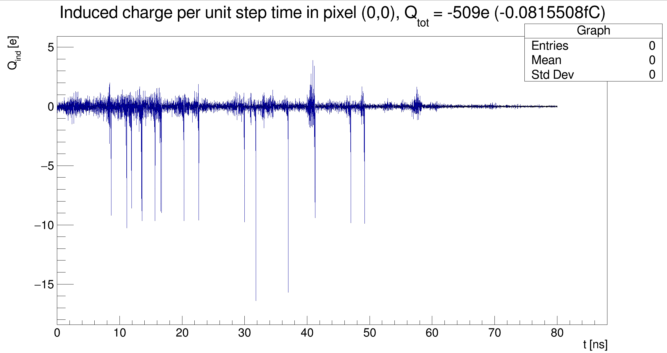
This graph is an average result of 10 events, indicating an pulse.
So I want to ask why or how to improve the first graph to show an obvious pulse.
Thanks in advance,
zhiliang
[DepositionPointCharge]
log_level = “INFO”
model = “fixed”
source_type = “mip”
position = -13um -8um 0um
[TransientPropagation]
temperature = 293K
charge_per_step = 10
timestep = 10ps
integration_time = 80ns
output_plots = 1
When I change charge_per_step = 10 and timestep = 10ps to charge_per_step = 1 and timestep = 0.1ps, it needs very long time and I have not gotten the result. So I don’t know whether it will improve the result.