Hi all,
I’ve recently been experimenting with different detector configurations and TCAD meshes in Allpix-Squared, and I have some questions about how the sizes of the simulated detectors are handled.
So, a simple detector model would probably contain some lines like this:
type = “monolithic”
number_of_pixels = 1 1
pixel_size = 50um 100um
sensor_thickness = 300um
My understanding of this is that the detector here will be a single pixel, but the pixel will be 50 microns wide in the x-direction, 100 microns wide in the y-direction and 300 microns deep in the z-direction. Finally, the “sensor_excess” and “sensor_excess_direction” parameters can be used to change the size further, but I haven’t been using it so it’s a bit beyond the scope of this post.
Now, when using a TCAD mesh, it has it’s own dimensions, right? I’ve noticed that sometimes my configuration complains when I give it a TCAD mesh that (apparently) is a different size or shape to the detector configuration, but that only results in (WARNING) level messages which don’t stop allpix from finishing the simulation. However, when I look the histograms showing something like the electric field magnitude after this, they have incorrect values for sizes of some axes. These aren’t even the values that I input into the model file but allpix complained were incorrect, they’re often new numbers entirely.
My first question is basically how can I use allpix to find the size and shape of the TCAD meshes I have? My ultimate goal is to study how parameters like charge collection efficiency behave when charges are deposited in different points in a strip and to do that I need to know that they will be placed where I want them to be, but the behaviour described above has given me some pause.
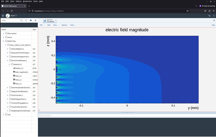
My second question is related to the above. Below I’ve attached a screenshot of a histogram showing an electric field mesh I’m using
This is a cross-section of several ITk strips at the edge of a sensor. I have this as a single TCAD mesh, but for my purposes I only really need a small subset of this mesh (the entire extent in y, but only the interval [-0.45,-0.35] in z).
My second question is: does allpix have any methods to consider just a subset of a mesh like this? As I’ve described above, changing the detector model parameters doesn’t do that, and moving the detector around doesn’t work either.
Cheers,
Damir
