Hello AllPixers,
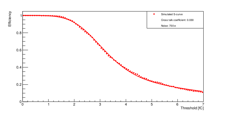
I have a question regarding the beta source measurements simulations. Is there anybody who used radioactive isotopes (eg. Sr90) as a particle type in AllPix^2 simulations? I think it behaves weird. When I used Sr90 as a source of beta particles and did threshold scan I got really strange result which doesn’t remind s-curve at all (see the first figure below). These beta particles, i.e. electrons, should have mean energy about 0.546MeV. So I tried to simulate electrons of this energy and got a result which looks fine (see the second figure). Don’t you know where might be the problem? I tried to change physics list FTFP_BERT_LIV to QGSP_BERT_HP, but this didn’t make any difference. 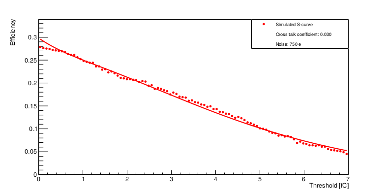
Hej Ondrej,
that indeed looks strange. Would you mind sharing the configuration files you used to produce above simulations?
Thanks!
/Simon
It seems that forum interface doesn’t allow to upload .conf file so I put all the necessary files on cernbox. Access link is here: https://cernbox.cern.ch/index.php/s/O01naa9rTmk6fge . Main .conf file is ITkSr90-ROW.conf
Oh, good catch. I enabled upload of conf files now. I’ll have a look at your configs and will come back to you, thanks!
Hi Ondrej,
first, not sure if related to your problem, but certainly an issue in your simulation, i noticed your e-field is facing the wrong way around - check the warning that says
|09:08:09.546| (WARNING) [I:ElectricFieldReader:dut] Electric field size is (1um,75.5um) but current configuration results in an field area of (75.5um,100mm)
                                                     The size of the area to which the electric field is applied can be changes using the field_scale parameter.
but what you really want is that the 1um direction (your missing coordinate in 2D) is oriented along the strip, so a message like Electric field size is (1um,75.5um) but current configuration results in an field area of (100mm,75.5um), i.e. flip the direction of strips in your model.
For finding the problem in the energy deposition I suggest altering your configuration and add the following keys:
[DepositionGeant4]
output_plots = true
output_plots_scale = 500ke
to generate plots showing you the total charge deposited by Geant4 in your sensor. Please observe that this is charge (electron/hole pairs), i.e. the energy divided by the energy required to generate one pair (3.6eV).
Does that get you anywhere? Maybe also compare with other sources, like Fe-55.
I realized that issue with electric field yesterday but I don’t think it will change anything. But of course I will fix it and try your suggestion. I will let you know if it helped somehow.
Hi Simon,
I was trying to change strips direction but without success (maybe I changed it but I still get the same warning from ElectricFieldReader). I don’t know what I am doing wrong. I thought that I should only change these lines:
number_of_pixels = 1280 1
pixel_size = 75.5um 10cm
into these:
number_of_pixels = 1 1280
pixel_size = 10cm 75.5um
However, as I was still getting that warning about not matching electric field I decided to sole it in a different way. I tried to convert .grd TCAD file again but with xyz = y x -z (instead of present xyz= x y -z), so that I don’t have to change strip orientation. The problem was that mesh_converter crashed with these parameters. I also tried combination xyz= z x y which is stated as an example in AllPix^2 user manual and converter crashed again. Parameters which worked for me was only original combination xyz = x y -z (it worked also without that - in front of z). Could you, please, give me some hint what might be wrong (still the goal for me now is either to change the strip direction or swap x an y for electric field)?
This is detector model file:
ITkStrip_280um.conf (197 Bytes)
This is configuration file for mesh_converter:
EF_ITkStrip.conf (191 Bytes)
I am not able to upload .grd, .dat nor .tdr files so that you could eventually check that conversion.
Hi Ondrej,
be sure to check what exactly the warning is. Because if it says
(WARNING) [I:ElectricFieldReader:dut] Electric field size is (1um,75.5um) but current configuration results in an field area of (100mm,75.5um)
                                                     The size of the area to which the electric field is applied can be changes using the field_scale parameter.
you have what you want: you “artifically” strech the 2D field (being 1um in thickness here) along the strip length (100mm), while the other two values match (75.5um vs 75.5um).
I can recommend swtiching
[ElectricFieldReader]
output_plots = true
and cross-check that the field is correctly displayed there.
Cheers,
Simon